
ICQUANZX DC Motor Speed Controller PWM 12V48V 40A Brush Motor Governor Speed Control Module
Electronics In this tutorial we will learn how to make a PWM DC Motor Speed Controller using the 555 Timer IC. We will take a detailed look how the 555 Timer PWM generator circuit works, how to use it for controlling the speed of DC motor and how to make a custom PCB for it. You can watch the following video or read the written tutorial below.

DC 5V 12V 12V 30A Dual Channel H bridge DC Motor Controller Driver Reversible PWM Speed Control
1. Connect multimeter red wire to the Voltage/Resistance port and the black wire to the ground port 2. Set multimeter to DC voltage 3. Separate the 2 power supply output wires and connect them to each of the multimeter terminals ensuring there's no contact between the ends of the power supply wires 4.

12v Dc Motor Controller Circuit Diagram Wiring Diagram and Schematics
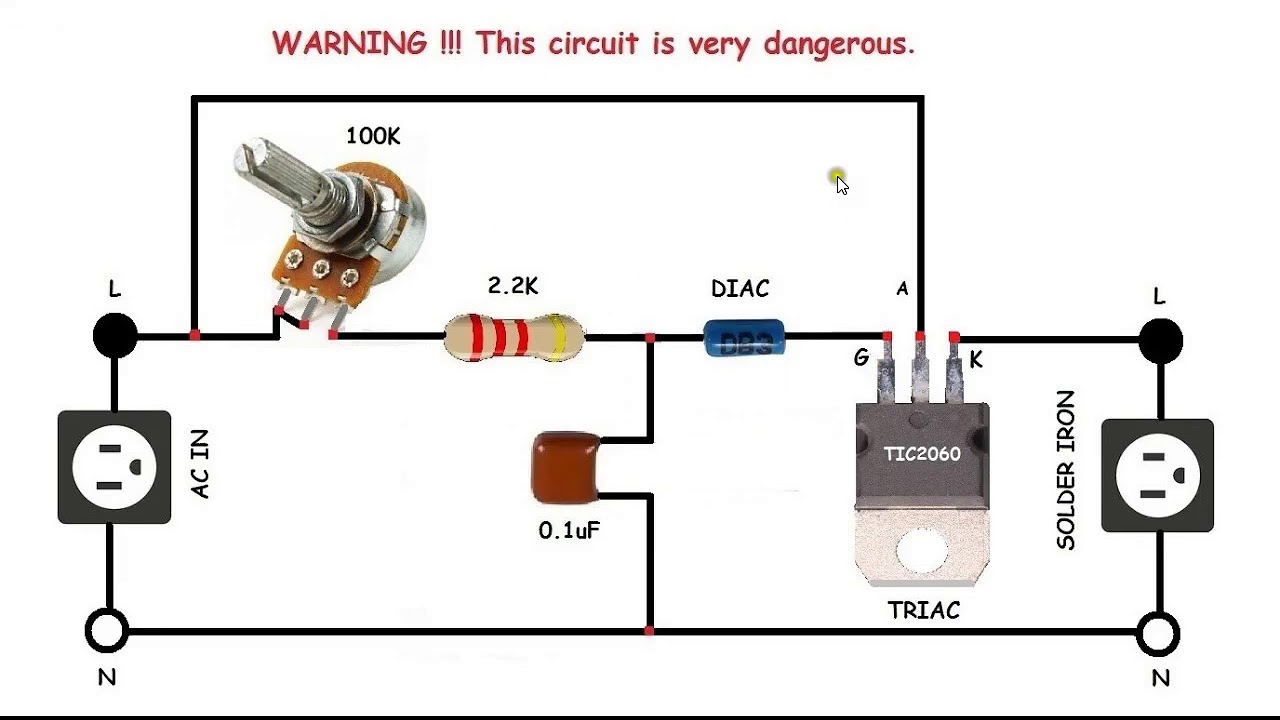
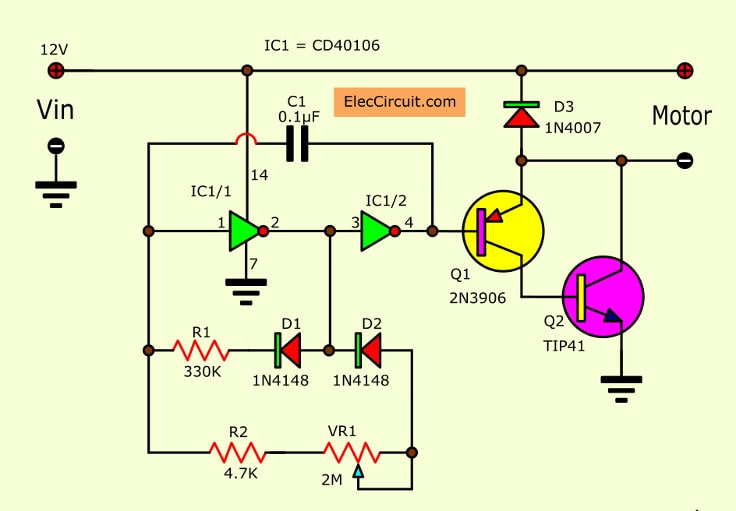
This is a speed motor controller circuit of a 12V DC motor. as SCR DC motor speed control circuit using IC-CMOS. You can adjust the speed of rotation of the spindle motor from 5 to 60 cycles per minute. How does it work. To begin with, the 12V AC voltage from the Secondary transformer comes to bridge diode-BD1.
Motor Speed Controller Circuit Diagram
Step 1: Component List Component List (motor control circuit): Power Supply 12v DC Regulator 7812 555 IC IN4001/4007 Diode Variable Resistor 50K Capacitor .1uf/104pf Capacitor .01uf/103pf Resistor 33ohm FET 75NF75 DC motor 12v Power LED Bread Board / Vero Board Jumper wire full details and video visit website c945 Ask Question
Simple 12V 9V 6V Motor DC Speed Control with PWM mode
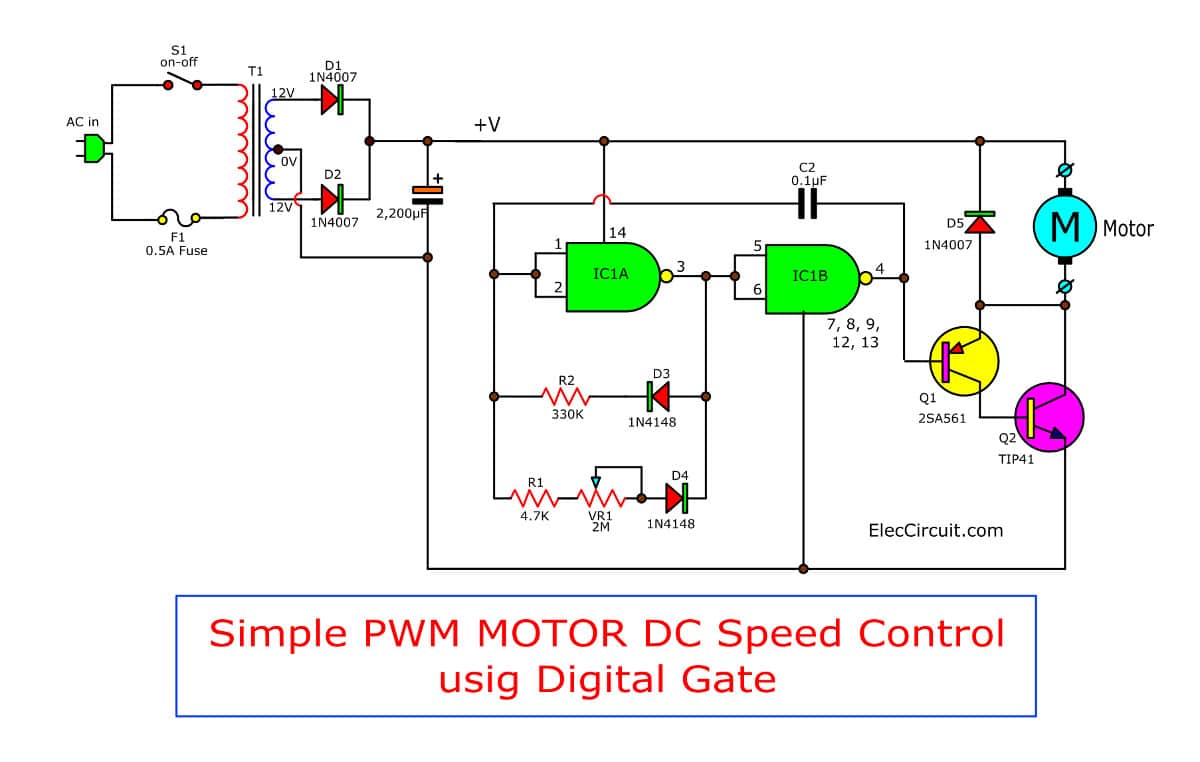
The circuit is designed to work with 12 volt DC motors having a peak current usage of below 5 amp. The mains AC supply is provided through the on/off switch S1 to the primary winding of the isolation and step-down transformer T1.
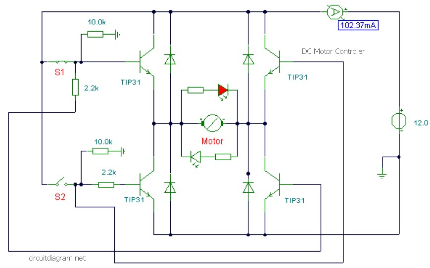
DC Motor Controller using Transistor TIP31 Electronic Schematic Diagram
How It Works When you buy a DC motor, you need to know what voltage DC motor work. Let's take a 12V DC motor as an example. When you power the 12V DC motor by a 12V power source: 12V and GND to the positive wire and negative wire, respectively: the DC motor rotates at maximum speed in the clockwise direction
Revizuire Nesatisfăcător terminat brushless dc motor controller schematic război Probleme
The circuit is based. #dcmotorcontroller#dcmotorspeedcontroller#Freewheelingdiode#pwmIn this video I have designed a PWM motor speed controller for DC motors.
12 volt DC motor speed controller with pulse
These are 12-volt DC variable-speed motor controller circuit using CMOS. They use the principle of PWM motor control mode. We can adjust the speed of 12V small motor. Even 6V or 9V Motor, this can be used, too. It is easy and uses a few components that IC digital and transistor driver as main. Table of Contents hide The motor speed control method
[DIAGRAM] 24v Dc Motor Speed Controller Circuit Diagram
A continuously variable DC voltage needs to be applied externally at pin #11 of the IC to generate proportionately varying PWM pulses. These pulses are further processed and are effectively used to control the connected motor speed right from zero to maximum. Referring to the figure we see, a dual timer IC 556 forms the heart of the circuit.

Fass Spende Persönlichkeit 12v dc motor speed controller Kosten Werkzeug Plaudern
On the one hand, that means that it can do a lot more than just vary the speed of a DC motor. This circuit will output a 12 volt current with a varying duty cycle. It can be used as 12 V DC: Motor Speed Controller; LED Dimmer; Heat controller for a Polystyrene Hot Wire cutter; voltage controller for an electrolytic etcher; and ; etc.
555 PWM DC motor controller circuit
Hello Guys today in this video I will show you How To Make Simple DC Motor Speed Controller Circuit Check the electronic components you need here: https://ww.

Simple Motor Control Circuit Diagram
L298N Driver. The L298N is a dual H-Bridge motor driver which allows speed and direction control of two DC motors at the same time. The module can drive DC motors that have voltages between 5 and 35V, with a peak current up to 2A. Let's take a closer look at the pinout of L298N module and explain how it works.
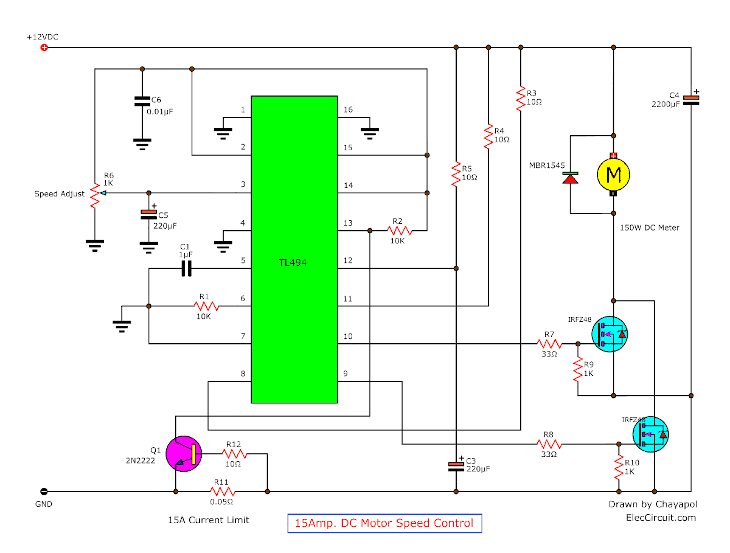
12V24V PWM Motor controller circuit using TL494IRF1405
Free Shipping Available. Buy Motor 12 Vdc Controller on ebay. Money Back Guarantee!
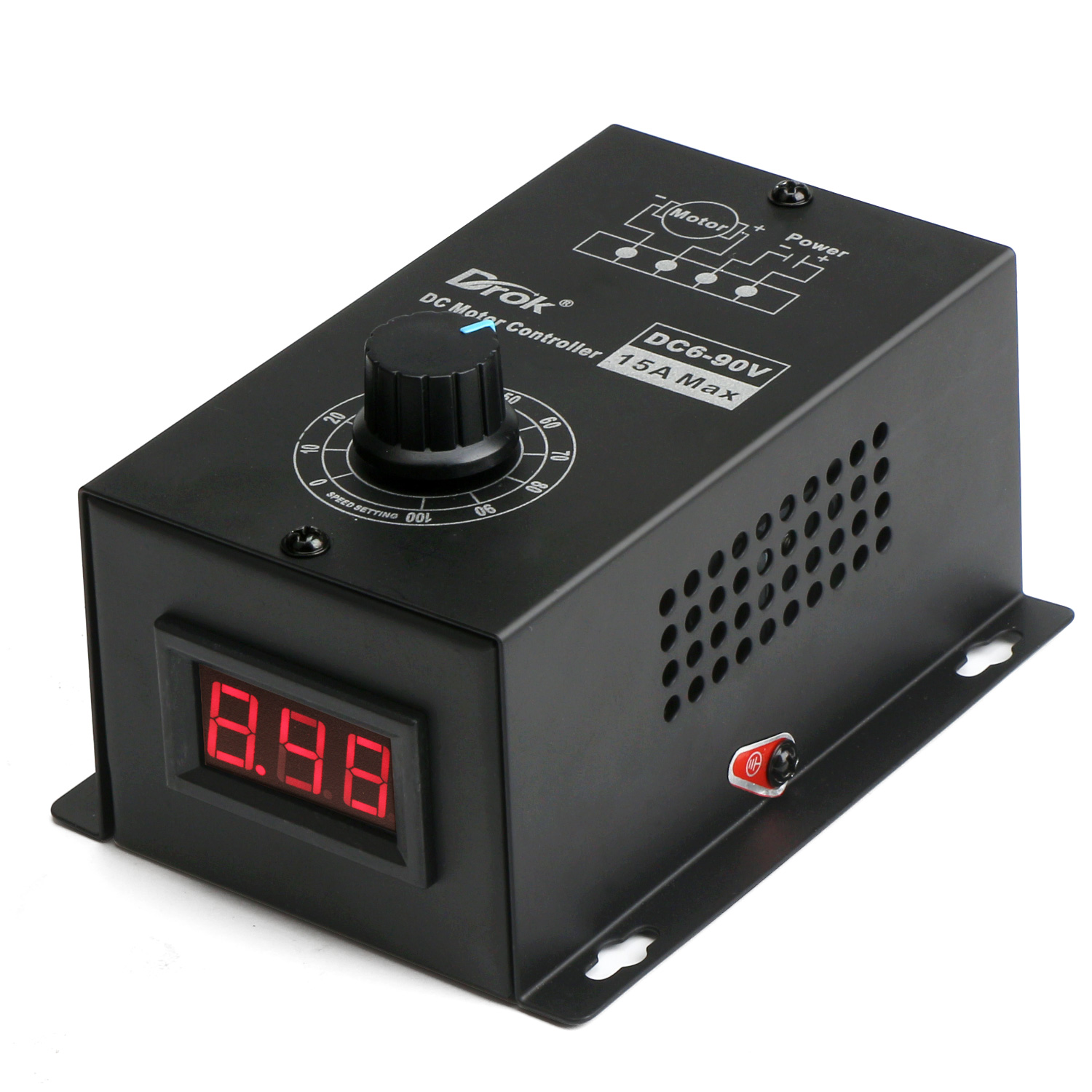
Drives & Motor Controls DC 630V 12V 24V MAX 8A Motor PWM Speed Controller With Digital Display
Solution: Place the potentiometer (POT) in series right after the 12V DC source's positive terminal. Explanation: If you look at the circuit to the left of our proposed POT and consider it a black box, the black box has some equivalent impedance.
12v Dc Motor Controller Circuit Diagram Wiring Flow Schema
Circuit Schematics: Here are the schematics of the DC Motor Speed Control Circuit. What is PWM? The word PWM is also known as Pulse Width Modulation. Suppose there is a voltage of 5 volts which is turning on and off in an interval.
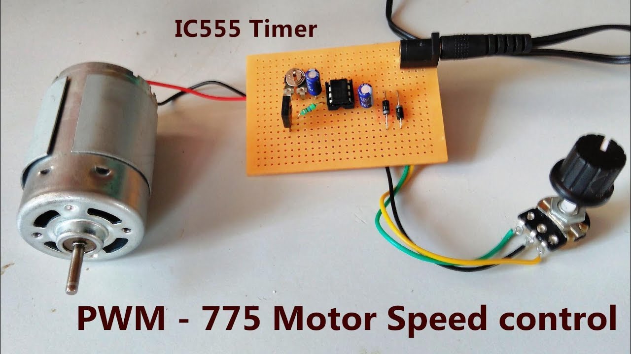
IC555 PWM 775 Motor Speed Controller 0.5v to 12v DC POWER GEN YouTube
This is a 12V DC motor speed control PWM circuit. Which using a TL494 (Switchmode Pulse Width Modulation Control IC) is a base for control DC Motor with pulse. Please detail more: - For Control speed motor 12V 150Wmax 15A. - R6 adjust speed motor. - Driver Motor by Mosfet IRFZ48.x 2pcs. - Control at Frequency 100HZ